
Below you will find the key ideas from Chapter 5 of CWISA-102.
Electromagnetic Spectrum
The electromagnetic spectrum is the complete range of all electromagnetic radiation.

Many technologies use electromagnetic spectrum frequency ranges such as:
- AM Radio
- FM Radio
- Wi-Fi, Zigbee, Bluetooth, LoRa
- Radar
- Light Bulbs
Frequency Bands
The predominant range for RF (Radio Frequency) communications spans from VLF (Very Low Frequency) to the lower end of EHF (Extremely High Frequency), with a particular emphasis between MF (Medium Frequency) and SHF (Super High Frequency).
Sine Waves (Ondas Sinusoidales)
A wave form is a representation of how alternating current (AC) (Corriente Alterna) varies with time.
A sine wave has several basic properties:
- Amplitude: The distance from zero to the maximum value of each alternation is called amplitude.
- Period:The time it takes for sine wave to complete one cycle is defined as the period of the waveform.
- Wavelength: Indicated by the greek lambda symbol. It’s the distance between one value to the same value on the next cycle.
- Frequency: The number of repetitions or cycle per unit time is the frequency typically expressed in cycles per second.
Wavelength
Average physical wavelength at 2.4 GHz is 12.5 cm and at 5 GHz the wavelength is 6 cm.

The lambda symbol is used to represent wavelength.

The length of the time required to complete one cycle is know as the period.
Wavelength Calculation
The formulas to calculate wavelength:
(In)= 18.11 / Frequency
(cm)= 30 / Frequency
| Frequency | Wavelenght |
|---|---|
| 800 MHz | 37.5 |
| 900 MHz | 33.33 cm |
| 2.4 GHz | 12.5 cm |
| 5.8 GHz | 5.17 cm |
| 6.5 GHz | 4.622 |
Frequency
Frequency is the number of times that a wave oscillates in one second. One oscillation in a second is know as a Hertz.
One cycle per second equals one hertz or 1 Hz.
Frequency is inverse related to wavelength.

Amplitude (Power Level)
Amplitude is the amount of signal energy. It is the strength or power of the signal. Common units of Amplitude are:
- Watts.
- Milliwatts (mW)
- Decibels to milliwatt.
Phase
Phase is a comparison of the cycle or period of different waves. A single wave does not have a phase. However, two waves will have a phase relationship with one other. Phase is measured in degrees of separation. Two sine waves can be 90, 180, 270 or 360 degrees out of phase.

RF Gain
Gain is the increase of RF signal strength or amplitude.
- Active Gain: Increasing power from the transmitter.
- Passive Gain: Shaping or focussing power from antenna.
This can be accomplished by increasing the transmit power of the RF radio and is know as active gain. Antenna gain will also increase the signal and this is known as passive gain
RF Loss
Loss is a decrease in signal amplitude often due to external interference or path loss. RF is caused by attenuation, absorption, and reflection.
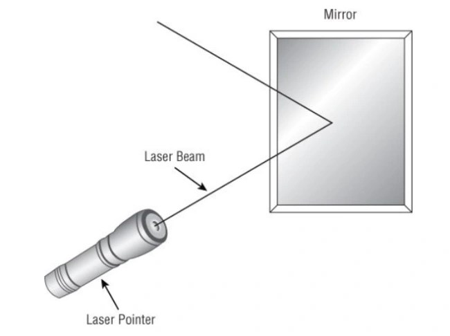
Reflection
Reflection occurs when a RF signal bounces off a smooth, non-absorptive surface, changing the direction of the signal. Reflective environments cause “multi path.” Since the object that causes reflection will normally be smooth and larger than the wavelength.
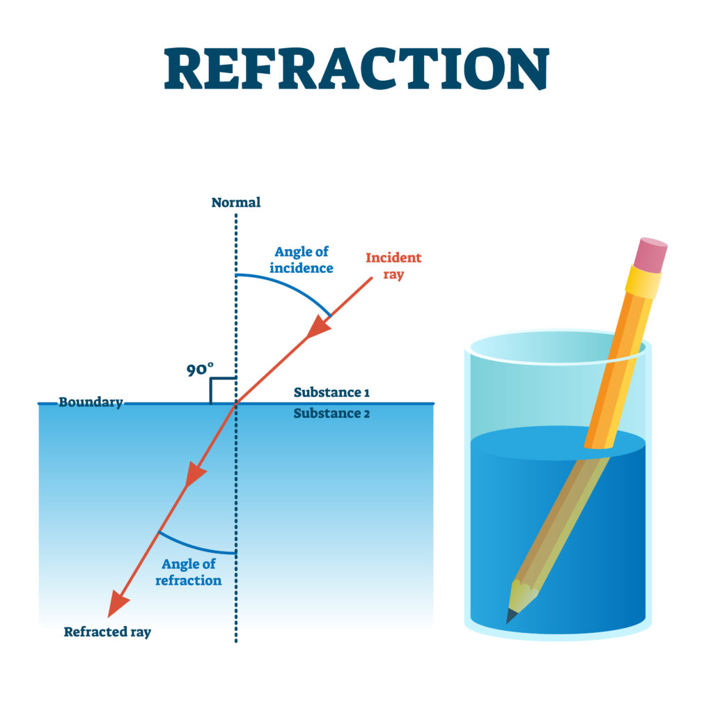
Refraction
Refraction occurs when the RF signal passes through a medium of different density than the original medium. Refraction causes the primary wave to change path direction. The best example of refraction is when visible light passes through a glass water. Refraction occurs when an RF Signal changes speed and is bent while moving through media of different densities.
Diffraction
Diffraction is a change in the direction (bending) of RF waves after passing by or through an obstacle.

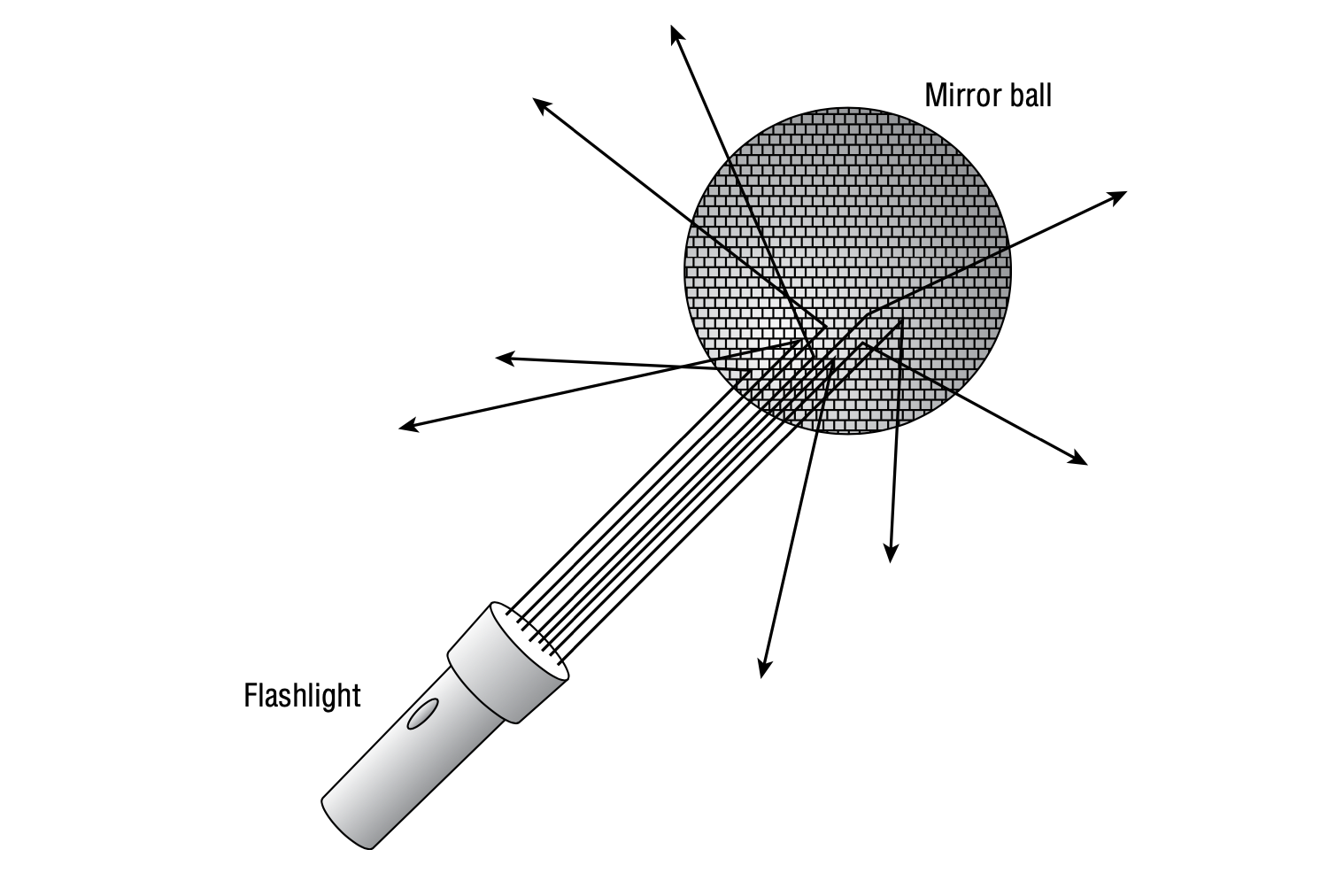
Scattering
Scattering is a type of reflection caused by uneven surfaces and increases echoes and multipath. Scattering can happen in a minor, almost undetectable way when an RF signal passes through a medium that contains small particles. Smog is an example of such a medium, rain and dust can cause scattering as well.
Absorption
Absorption is the conversion of the RF signal into heat. This conversion happens because the molecules in the medium through which the RF signal is passing cannot move fast enough to “keep up” with the RF waves.
RF Propagation
Waves move away from the source. Similar to waves created by a rock being thrown into a calm lake.
Free Space Loss
Free Space Loss is a measure of how much signal remains with increasing distance in a free space. Mathematically, the 2.4 GHz signal would travel twice as fas as 5 GHz, and provide the same signal loss.

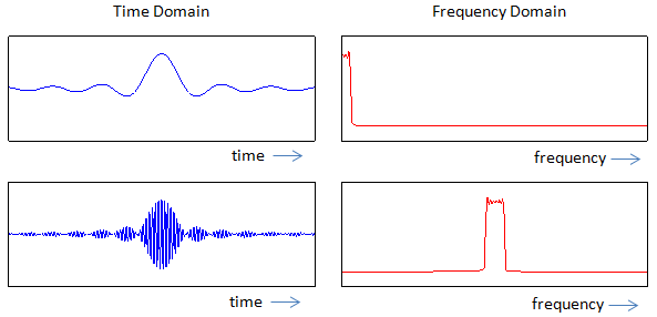
RF in the Time Domain
Time domain tools, such oscilloscopes, are used to measure how a signal amplitude changes over time. They are not used much by engineers or administrators during wireless surveys or implementation, but they are used frequently by wireless engineers in laboratory test environments.
RF in the Frequency Domain
Spectrum analyzer are much more familiar to wireless engineers because this is how we visualize the RF medium to troubleshooting our network no a daily basis.
Basic types of Modulation
- Baseband Signal: Original data bits in the radios.
- Amplitude Modulation: Varies the Amplitude of the carrier signal to encode data.
- Frequency Modulation: Varies the Frequency of the carrier signal to encode data.
- Phase Modulation: Phase Shift Keying.
Modulation is a process by which some property of a carrier signal is modified to represent digital bits. Amplitude, frequency and phase are the three basic elements of a waveform that can be varied.
Chirp Spread Spectrum
Chirp Spread Spectrum used by LoRa modulation within LoRaWANs is different from others. Rather changing the waveform, per se, it changes how energy is swept across the channel bandwidth.

PSK Modulation Constellations
Module constellations serve as a useful visual tool for comprehending modulation. These constellations illustrate the in-phase and quadrature components of a carrier wave, with rotation around the center axis depicting the phase components of the wave. For instance, in the BPSK (Binary Phase Shift Keying) constellation, there are only two phases plotted along the in-phase axis, reflecting a binary modulation with a 180-degree phase shift.
In the case of QPSK (Quadrature Phase Shift Keying) modulation, the constellation displays four possible data points, corresponding to phase shifts of 0, 90, 180, and 270 degrees. Since there are four potential data points, QPSK can represent 2 bits of information. While BPSK provides a wider margin of error for the receiver (180 degrees), QPSK has a narrower margin of error (90 degrees) due to the increased number of possible data points. However, QPSK is also twice as efficient as BPSK because the same carrier signal can convey 2 bits instead of 1

QAM Modulation Constellations
QAM (Quadrature Amplitude Modulation) is a high-efficiency wireless modulation type commonly utilized with OFDM (Orthogonal Frequency Division Multiplexing). QAM incorporates both a phase and amplitude component, allowing it to represent a greater number of data points. For example, 16-QAM can represent 16 different data points, corresponding to 4 bits of information (2^4 = 16). Similarly, 64-QAM includes 64 data points, representing 6 bits of information (2^6 = 64). The increased number of bits enables QAM to achieve higher data rates, making it a valuable modulation scheme in modern wireless communication systems..

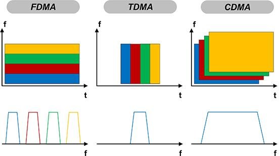
TDMA and FDMA
The first method is Time Division Multiple Access (TDMA), where all wireless stations on the network share the same transmission frequency. TDMA was utilized in legacy 2G GSM cellular networks but continues to exist in various other technologies today, such as point-to-point wireless networks. In TDMA, each device is allocated a specific time slot for transmission.
On the other hand, Frequency Division Multiple Access (FDMA) provides separate sub-channels for each transmitting device, instead of assigning time slots. FDMA divides the frequency spectrum into distinct frequency bands, and each device is allocated a dedicated frequency band for its transmission.
The other notable modulation method is cellular networks is Code Division Multiple Access(CDMA) uses a walsh code to convert data into oa series of chips.

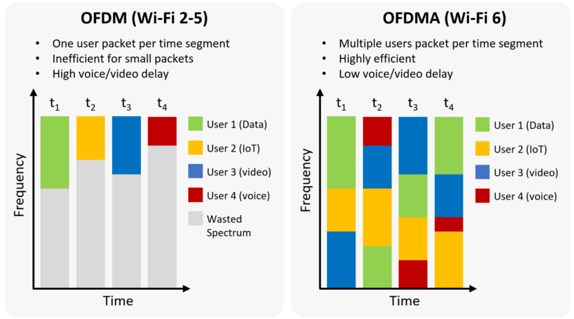
OFDM and OFDMA
Orthogonal Frequency Division Multiplexing (OFDM) is a modulation technique that divides a specified frequency space into subcarriers. These subcarriers are small divisions within the operating channel, strategically spaced apart to prevent self-interference. In OFDM, all data subcarriers collaborate to simultaneously transmit data. Each subcarrier has the capability to convey different pieces of data, enhancing transmission speeds, or replicate the same data to ensure reliability. The specific code scheme employed determines how the data is distributed across the subcarriers. OFDM is widely used in wireless communication systems for its efficiency in handling multipath interference and enhancing overall data transmission performance.
Orthogonal Frequency Division Multiple Access (OFDMA) is a variation of OFDM (Orthogonal Frequency Division Multiplexing) that enables data transmissions to multiple separate receivers simultaneously. In traditional OFDM, a transmitter needing to send distinct pieces of data to multiple receivers would have to transmit to each receiver one at a time. OFDMA addresses this challenge by allowing a transmitter to divide its channel into multiple pieces in the frequency domain, enabling the simultaneous transmission of data to multiple receivers. This capability enhances the efficiency and throughput of data transmission in wireless communication systems..
Frequency Hopping
Frequency-Hopping Spread Spectrum (FHSS) devices mitigate interference from other devices by rapidly switching from one channel to another while transmitting information. Typically, during data transmission, they occupy a minimal amount of channel space, often using only 1 out of 3 MHz of frequency space. The duration that an FHSS transmitter spends on a single channel is referred to as dwell time. An example of FHSS technology is Bluetooth, which employs Adaptive-Frequency Hopping Spread Spectrum.
Units of RF Measurement
Absolute Units
- Wats.
- Milliwats.
- dBm.
Relative Units
- dB: Decibel: Basic unit of measurement that quantifies changes in power
- dBi: Decibel relative to an Isotropic radiator.
- dBd: Decibel relative to an dipole antenna.
dBi and dBd
dBi and dBd are used to measure antenna gain
dBi: Decibel relative to an isotropic radiator, used to measure passive antenna gain
dBd: Decibel relative to a half-wave dipole. Half-wave dipole= 2.15 dBi
Conversion Chart (dBm/mW)

IR, EIRP and ERP
- The intentional Radiator: in a wireless transmission system, is the point at which the antenna is connected back to the radio itself, does not include antenna.
- Equivalent Isotropically Radiated Power (EIRP): Energy measured at antenna output (compared to an isotropic radiator)
- Equivalent Radiated Power (ERP): Energy measured at antenna output (compared to dipole antenna).


Deja un comentario