
RF Signal Radiators
Below you will find the key ideas from Chapter 6 of CWISA-102.
- Incidental Radiator: Electric o mechanic devices that generate RF energy and radiate it into the environment, but they are not designed to produce RF energy.
- Unintentional Radiator: Electric devices that generate electrical or radio frequency signals that are intended to be contain within the system or conductive link and not radiated into the environment, but they may emit some RF Energy in spite of the intended design.
- Intentional Radiator: Electric devices designed to generate radio frequency signals and transmit them into the environment, but don’t include the antennas.
Logical Radio
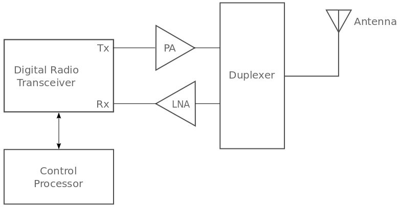
Amplifiers in radio frequency (RF) systems consist of components like Low-Noise Amplifiers (LNAs), Intermediate Frequency (IF) amplifiers, and others. The primary function of an amplifier is to enhance the amplitude of the RF signal, either for transmission or during reception.
LNAs are integral to the receive chain, positioned at or near the point where the signal enters the radio chain. The role of an LNA is to amplify the signal for further processing while introducing minimal noise. The use of LNAs allows receivers to process very weak signals. An LNA may amplify a signal by 50dB or more, with a noise figure as low as 1dB. The noise figure of an LNA is crucial, as it directly impacts the signal-to-noise ratio (SNR). For instance, if a signal is -90dB with an SNR of 10dB and is amplified by 50dB with a noise figure of 1dB, the resulting signal will be 40dB with an SNR of 9. If the amplifier had a noise figure of 5dB, the resulting SNR would only be 5dB.
Filters are employed to restrict the signal to the desired frequencies. Before discussing filters, understanding the concept of Intermediate Frequency (IF) is essential. Many radio systems down-convert the received signal to an IF for simpler processing, and the IF is subsequently processed for actual demodulation. This approach offers several advantages.
Returning to filters, they play a crucial role in image rejection, preventing unwanted frequencies from introducing errors during conversion. Filters also contribute to selectivity in isolating specific frequencies.
Antenna Function
Antennas function by transforming electrical current into waves. They are bi-directional, meaning they can both transmit and receive radio waves. Radios are responsible for modulating a baseband signal onto electrical current, typically transmitted over a guided medium like a metallic cable. As the electrical current passes into the antenna, it generates electromagnetic waves or radio frequency waves.
Electromagnetic Radiation
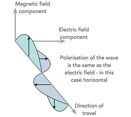
Electric and magnetic field are perpendicular to one another moving into space away from the source. Electric Field (E Plane) Magnetic field (H plane).
Pasive Gain
Antenna gain is measured in relative units:
- Relative to an isotropic radiator (dBi)
- Relative to half-wave dipole antenna (dBd)
They passively focus the energy; they do not actively add energy.
Antenna Charts
Azimuth charts show the propagation pattern from top-down perspective and are also called horizontal charts. Elevation chart shows the propagation pattern from a side perspective and are also called vertical chart
Polarization
Polarization is determined by the electric field (E-field). In the case of most Wi-Fi antennas, polarization is linear, indicating that the wave oscillates either in an up-and-down or side-to-side manner. When the E-field is oriented vertically (up and down, relative to the Earth’s surface), the electromagnetic waves are said to have «vertical polarization.» On the other hand, if the E-field is oriented horizontally (side to side, relative to the Earth’s surface), the electromagnetic waves are said to have «horizontal polarization.»
Omnidirectional Antenna
- 360º Horizontal coverage.
- Vertical coverage varies with antenna gain.
- Low gain omnidirectional antennas provides wide vertical beamwidth.
- High gain omnidirectional antennas provides narrow vertical beamwidth.

Semi directional Antenna
- Provides more gain in general directions than omni antennas.
- Vertical and horizontal beamwidth often varies between 180º and 15º depending on gain.
- Pannel, Patch, Sector and Yogi are common semi directional antennas.

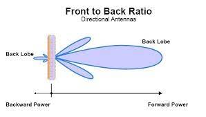
Highly directional Antenna
- Used for long range outdoor link.
- Vertical and horizontal beamwidth usually less than 25º.
Onboard Antennas and connectors
Many small form factor devices use integrate PCB (printed circuit board) antennas.
Amplifiers
Amplifiers enhance the signal strength before it reaches the antenna, while attenuators reduce it. Attenuators are employed to maintain the Effective Radiated Power (ERP) and Effective Isotropic Radiated Power (EIRP) within regulatory limits when the output power of the wireless transmitter cannot be adjusted low enough. When utilizing amplifiers, it is crucial to ensure that the input signal is low enough to prevent signal compression.
Signal compression occurs when the input signal is sufficiently high, causing the top of the signal to become «flattened» or compressed.
Line of sight (LoS)
- Short range (e.g. indoor) RF LoS not requiere visual LoS.
- Long rage RF LoS require obstruction free visual LoS.
- Obstruction in or near the LoS path will degrade or prevent RF communication

Fresnel Zone
The first fresnel zone should be at least 60% clear of obstructions. Most engineers recommend 80% clearance for added stability and protection.
Inverse Square Law
As the distance doubles, the energy spreads over 4 times the area, resulting in one quarter (1/4) of the original density. Power density decreases as the wavefront moves outward.

Common RF Connectors
- **N-Type: **This connector type is the largest of the common wireless RF Connectors and is used in outdoor equipment with high transmit power.
- RP-SMA: Reverse Polarity is small antenna connector type often used for indoor APs.
- RP-TNC: This connector is similar to SMA, though slightly larger.
- MCX/MMCX:There are smaller connector types, often used for external antennas or external WLAN cards.
- U.FL This connector is common for internal wireless chips used for laptops.

Lighting Arrestors
Lightning arrestors are installed to redirect or shunt electric current caused by close proximity lightning strikes. They are not designed to protect against direct lightning strikes. Unfortunately, if an antenna is directly struck by lightning, it will likely be damaged, and the attached equipment may be lost as well. Lightning arrestors are installed in series between the antenna and the base station or bridge. Additional components such as connectors or amplifiers, if placed between the arrestor and the antenna, will not be protected by the lightning arrestor. Therefore, it is advisable to install the lightning arrestor closer to the antenna with nothing in between.
PTP Links
There are two forms of bridging connectivity
- Point to Point.
- Point to MultiPoint.
Point-to-Point connections can be used to connect two workgroups or two building together. PtP connections may use: - Directional Antennas.
- Encryption to protect the wireless data.
Configuration PtP bridges settings may include power output adjustments and manual entry of MAC addresses.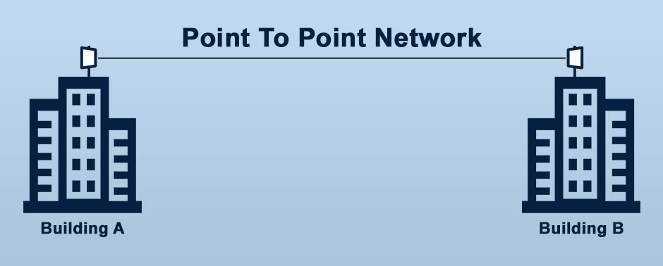
Point to Multipoint connection can be used to connect multiples workgroups or multiple buildings together. PtP connections can may use directional and omni-directional antenna together to get the best coverage.
The central bridge configuration often requires MAC addresses of remote bridges to be entered manually. The MAC address of the central bridge must also be entered manually at each remote bridges. Encryption should be enabled on the bridged connections.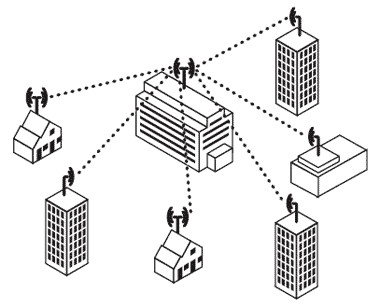
Ad-Hoc vs Mesh
In wireless networks and ad-hooc wireless network is a group of wireless devices that dynamically create a network without requiring an existing network infrastructure. Many wireless link are categorized as ad-hoc network links including:
- Bluetooth and other peripheral wireless device connections.
- 802.11 direct wireless links between client devices without access points.
- Vehicular ad-hoc networks (VANETs). Used to communicate with other vehicles and roadside equipment.
- WSN sometimes used self-forming and self-healing ad-hoc networks.
Ad-hoc networks may be subcategorized as stationary ad-hoc networks and mobile ad-hoc networks (MANET).
Stationary ad-hoc devices are those formed between devices, and devices do not move at all or move very short distances while participating in the network.
MANETs, as they are usually conceptualized, involve more dynamics with devices coming and going from the network.
An example of stationary ad-hoc network would be two mobiles phones connected by either bluetooth or wifi, while the user stay in the same room sharing photos or playing collaboratives games.
An example of MANET would be WSN where some or all sensors are mobile, and the sensor form an ad-hoc.
Two essential differentiators exist between ad-hoc networks and mesh networks. - Mesh network nodes typically have more than one radio today. With this implementation the mesh node can communicate with multiple other nodes concurrently.
- One or more, mesh nodes will have connection to the rest of the network and possibly to internet.

Deja un comentario